Pressure Vessel Design and Manufacturing
ME421L Mechanical Design | Duke University
For this mechanical design project, my team designed and manufactured a compact pressure vessel for laboratory pressure testing. The vessel was required to hold 50–60 cc of liquid at 750 psig, include a working O-ring seal, use a threaded connection, and remain manufacturable within a $100 McMaster-Carr budget. The final design used a turned 6061-T6 aluminum body, removable aluminum end cap, Buna-N static face seal, six 1/4-20 alloy steel socket head cap screws, and a 1/4 in NPT port for the provided Swagelok fitting. The project combined hand calculations, bolted joint analysis, O-ring gland design, FEA validation, CAD drawings, and hands-on machining in the Duke Student Machine Shop.
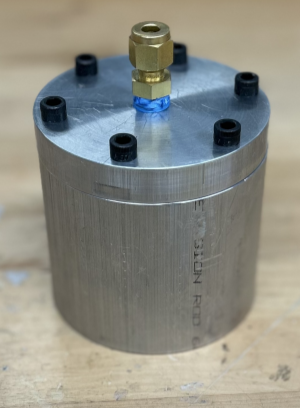
Final Machined Vessel
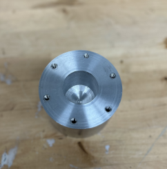
Final Machined Body
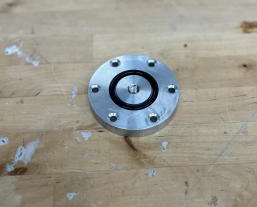
Final Machined Lid
Mathematical Analysis
Section 1: Internal Volume and Pressure Load
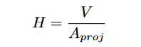
The internal cavity was sized to meet the required 50–60 cc liquid volume while keeping the vessel compact and machinable from round aluminum stock. Using an internal clear diameter of 1.50 in, the required straight-wall cavity height was calculated from the target volume.
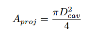
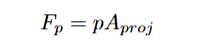
This pressure end force became the governing load for the bolted cap design, since the fasteners had to maintain enough clamp force to prevent the cap from separating under pressure.
Section 2: O-Ring Seal Design
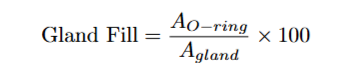
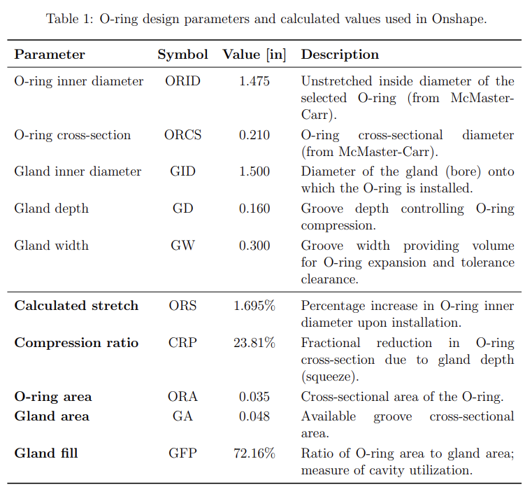
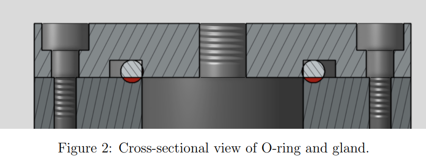
The vessel used a static face seal between the removable lid and the main body. A Buna-N O-ring was selected for availability, cost, and compatibility with room-temperature liquid pressure testing. The groove geometry was designed around three sealing parameters: O-ring stretch, compression ratio, and gland fill.
These values placed the seal within the recommended design range for a static face seal, balancing leak prevention, compression set risk, and available groove volume.


Section 3: Bolted Joint and Preload
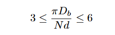
The removable cap was secured using six 1/4-20 ASTM A574 socket head cap screws. The bolt circle was selected to provide even clamp distribution while maintaining clearance from the O-ring groove and vessel edge.
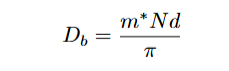
The spacing ratio ensured that the bolts were neither too tightly packed nor too far apart. A midrange target spacing ratio of m∗=4.5 was used to size the bolt circle.
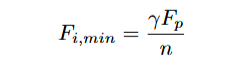
Once the bolt layout was selected, the pressure end force was used to determine the minimum clamp force required to prevent cap separation.
Here, the pressure force acting on the cap, n is the number of bolts, and γ is a margin factor used to provide additional clamp capacity beyond the exact pressure load.
Section 4: Bolt Preload and Installation Torque
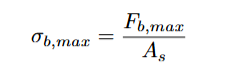
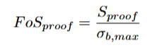
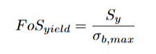
After selecting the bolt preload, the maximum bolt stress was checked to ensure that the fasteners remained below their proof and yield limits. This step verified that the bolts could provide the required clamping force without being overstressed.
These calculations confirmed that the selected fasteners had sufficient margin under the combined preload and pressure-induced loading. The design achieved a factor of safety of approximately 1.33 against proof loading and 1.52 against yielding, which exceeded the minimum target used for the preloaded joint.
Section 5: Bolt Stress and Safety Factor
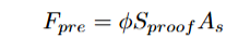
The minimum clamp force was then compared against the actual preload selected for the six 1/4-20 ASTM A574 socket head cap screws. The preload was based on the proof strength of the fastener and the tensile stress area of the bolt. After selecting the preload, the installation torque was estimated using a standard torque-preload relationship.

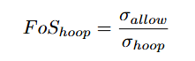
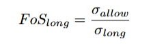
The pressure vessel body was also checked for pressure-induced wall stress. The hoop and longitudinal stress margins were evaluated using the selected 6061-T6 aluminum body dimensions to confirm that the cylindrical wall had sufficient strength under the 750 psig internal pressure.
The calculated wall stresses were well below the conservative allowable stress for 6061-T6 aluminum. The final design had a hoop stress factor of safety of approximately 20 and a longitudinal stress factor of safety of approximately 118.5, indicating that the wall thickness had significant structural margin. In practice, the final wall thickness was driven not only by pressure stress, but also by O-ring land width, tapped hole engagement, fitting clearance, and machinability.
Section 7: FEA Validation
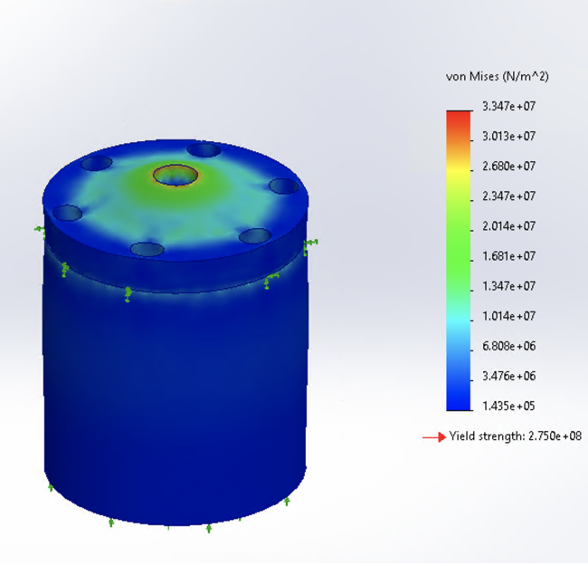
Finite element analysis was used to supplement the hand calculations and visualize stress concentrations in the final geometry. The model applied 750 psig internal pressure to the wetted surfaces and evaluated the body, cap, bore, fitting port, and bolted interface.
The FEA results confirmed that the highest stresses occurred near expected geometric discontinuities, including the tube fitting hole, bore, and fillets. The flange stresses remained modest, and cap deflection was below the available O-ring compression, allowing the seal to remain energized under pressure.
Section 8: Machining and Manufacturing
After the design was validated through hand calculations and FEA, the pressure vessel was manufactured in the Duke Student Machine Shop. The final part required turning the 6061-T6 aluminum round stock, boring the internal cavity, machining the O-ring groove, drilling and tapping the bolt circle, machining the removable lid, and adding the 1/4 in NPT port for the Swagelok fitting.
The design was intentionally simplified for manufacturability. An early concept used an external flange with through-bolts and nuts, but this would have required wider stock, increased cost, and added machining time. The final tapped-hole design reduced material usage, simplified the machining process, and remained structurally adequate based on the bolted joint analysis.