ELECTRIC GLIDER PERFORMANCE IMPROVMENET
(Senior Capstone Project 2025-2026)
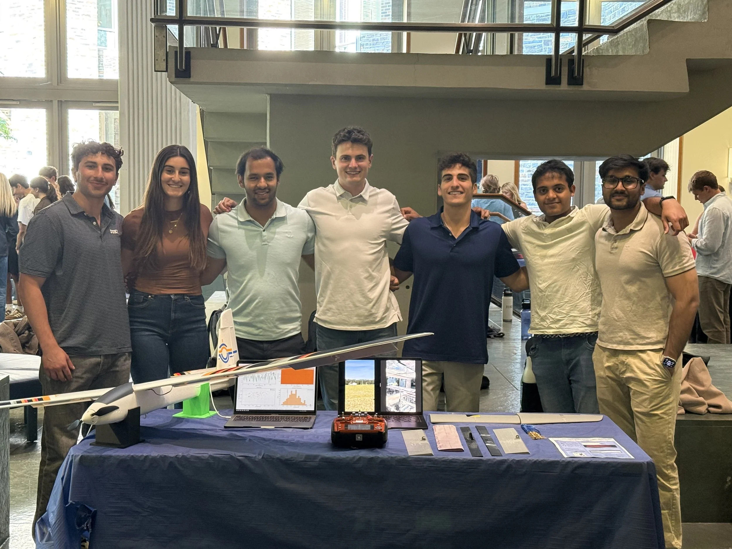
As Project Manager for Duke University’s Electric Glider Performance Improvement senior design team, I led a seven-person effort to design, manufacture, and flight-test a custom flap system for a commercial RC electric glider. Our client, Dr. Michimasa Fujino, founder of Honda Aircraft Company, challenged us to investigate how low-cost aerodynamic modifications could improve slow-flight performance through a process similar to real aircraft development. The project targeted a 10% reduction in stall speed and a 5% reduction in sink rate, requiring our team to combine aerodynamic analysis, CAD, XFOIL, 3D CFD, wind tunnel testing, structural design, avionics integration, and instrumented field testing into one working aircraft system.
Engineering Challenge
The core engineering challenge was balancing lift improvement against the penalties that come with modifying a lightweight aircraft. Adding a flap can increase the wing’s camber and raise the maximum lift coefficient, allowing the aircraft to fly at a lower stall speed. However, flap deployment can also increase drag, shift the center of gravity, add structural mass, complicate control behavior, and introduce uncertainty during flight testing.
Because the aircraft was a commercial RC glider, the team also had to work within the constraints of an existing airframe. The baseline wing did not include stock flaps, and the manufacturer did not provide detailed aerodynamic geometry. That meant the team had to reconstruct the wing, approximate the airfoil, select a flap concept, design new control surfaces, and integrate sensors without compromising the glider’s ability to fly safely. The final solution had to be lightweight, manufacturable, structurally reliable, and measurable through flight testing.
Design & Analysis Process
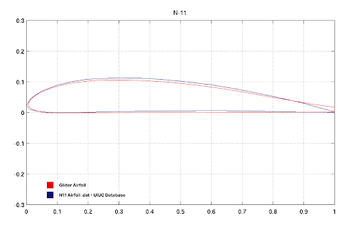
The design process began with understanding the baseline aircraft and building a usable aerodynamic model. Since the original wing geometry was not available, the team traced the airfoil profile and compared it against known airfoils from the UIUC database. This process led to the N11 airfoil as a close approximation of the Skynetic glider’s wing section, which allowed the team to begin early XFOIL simulations and estimate how changes to the trailing edge could affect lift and drag.
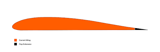
The early aerodynamic analysis showed that modifying the trailing edge could increase lift and improve stall behavior. From there, the team evaluated multiple flap concepts, including plain, split, slotted, and Fowler-style flaps. Although more complex flap systems offered higher theoretical performance, they also introduced added weight, mechanical complexity, and greater integration risk. For a foam RC glider with a limited project timeline, simplicity and reliability became critical design drivers.
The team ultimately moved toward a simpler trailing-edge flap approach. Instead of using a true flaperon that combined flap and aileron motion into one surface, the final design separated the flap and aileron functions. This allowed the flap to deploy symmetrically for lift generation while the ailerons preserved independent roll control. This separation made the system easier to control, easier to test, and easier to interpret during flight data analysis.
Fabrication & Integration
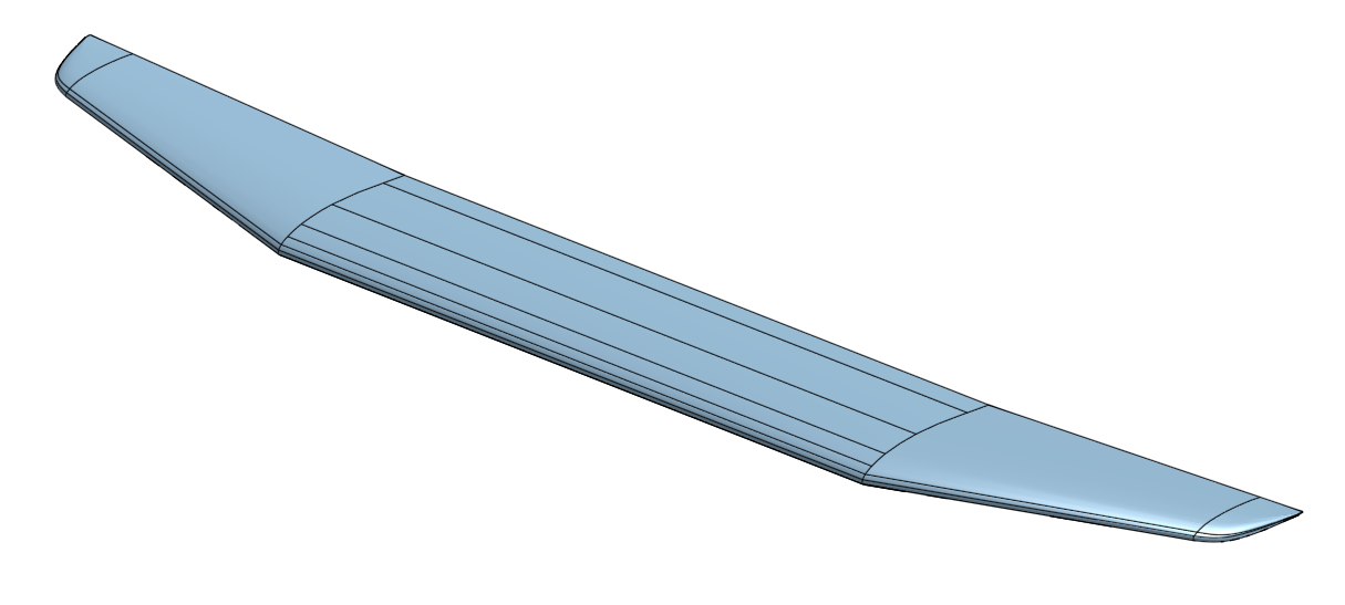
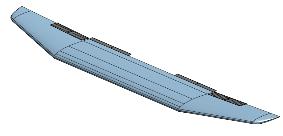
Once the aerodynamic concept was selected, the design moved from analysis into CAD reconstruction, prototyping, and physical integration. One of the first challenges was that the commercial glider wing did not come with usable manufacturer geometry, so the team had to recreate the wing manually. To do this, sections of the wing were physically cut and traced at different spanwise locations. Those cross sections were then brought into CAD and lofted together to approximate the three-dimensional wing geometry. This reconstructed model became the foundation for flap sizing, surface integration, and later aerodynamic visualization.
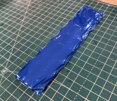
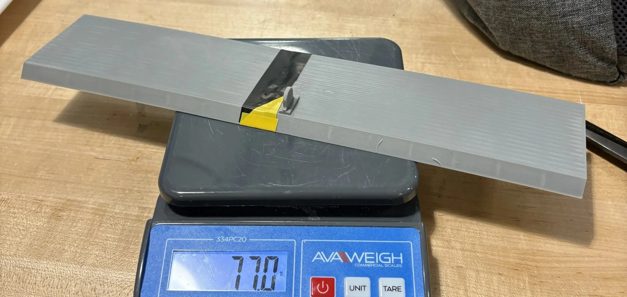
The control surface design also went through several material iterations. Early prototypes explored foam because of its low weight, but foam made it difficult to maintain precise edges, angles, and repeatable geometry. The team also explored a wood frame wrapped in Monokote, which offered a lightweight structure and cleaner geometry, but introduced attachment and integration challenges. After these prototypes, the design moved toward CAD-modeled and 3D-printed PLA components because they allowed rapid iteration, accurate cross-sectional geometry, repeatable manufacturing, and stronger attachment features.
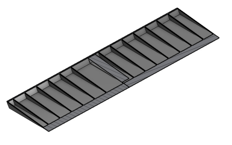
The final wing modification used custom-designed flaps and improved ailerons manufactured through additive manufacturing. Because of printer bed limitations, each control surface was split into multiple sections, then joined using slide-in interlocking features and plastic-welded seams to preserve alignment and structural continuity. This approach made it possible to manufacture full-span control surfaces while still keeping the geometry consistent across the wing.
Weight remained a major design constraint throughout fabrication. Any added mass would increase stall speed, worsen sink rate, or shift the center of gravity enough to affect stability. To reduce weight while maintaining stiffness, the control surfaces used hollowed internal geometries and ribbed structures. The flap and aileron cross sections were also designed around mechanical deflection limits, with the flap capable of approximately 30 degrees of maximum deflection and the aileron capable of approximately ±40 degrees.
Although PLA provided the best balance of manufacturability, accuracy, and iteration speed for the timeline of the project, it was not necessarily the ideal final aerospace material. A logical next step would be to explore composite options, such as fiberglass or carbon fiber layups over lightweight cores or printed molds, to preserve the geometric accuracy of the PLA design while reducing mass and improving stiffness. This would directly address one of the key tradeoffs observed during testing: the need to increase lift without adding enough weight or drag to reduce glide efficiency.
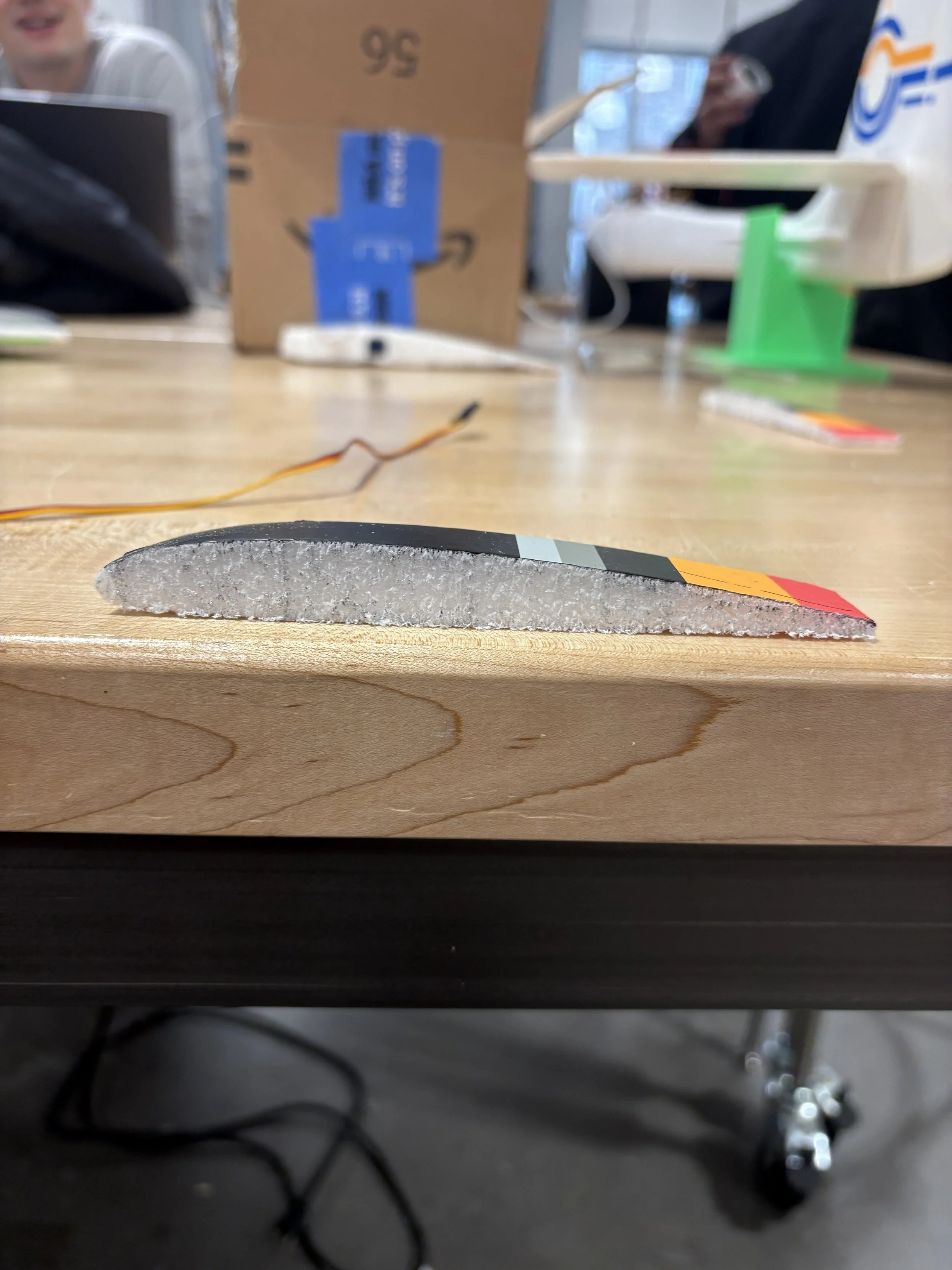
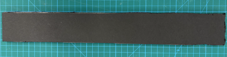
Foam Prototype
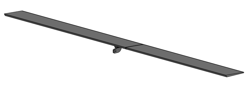
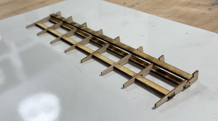
Laser Cut + Monokote Prototype
PLA Prototype
Testing & Results
With the modified wing fabricated and integrated into the aircraft, the team moved into experimental validation. Testing included both wind tunnel testing and outdoor flight testing, with the goal of comparing the original baseline glider against the modified configurations.
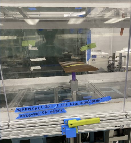
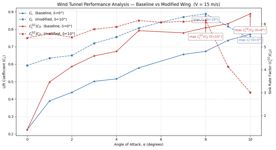
Wind tunnel testing provided a controlled way to compare aerodynamic behavior before relying entirely on outdoor flight data. It allowed the team to evaluate lift and drag trends across different angles of attack and compare the baseline and modified wing geometries under repeatable conditions. This was especially important because full aircraft flight testing was affected by wind, gusts, pilot input, and center-of-gravity changes.
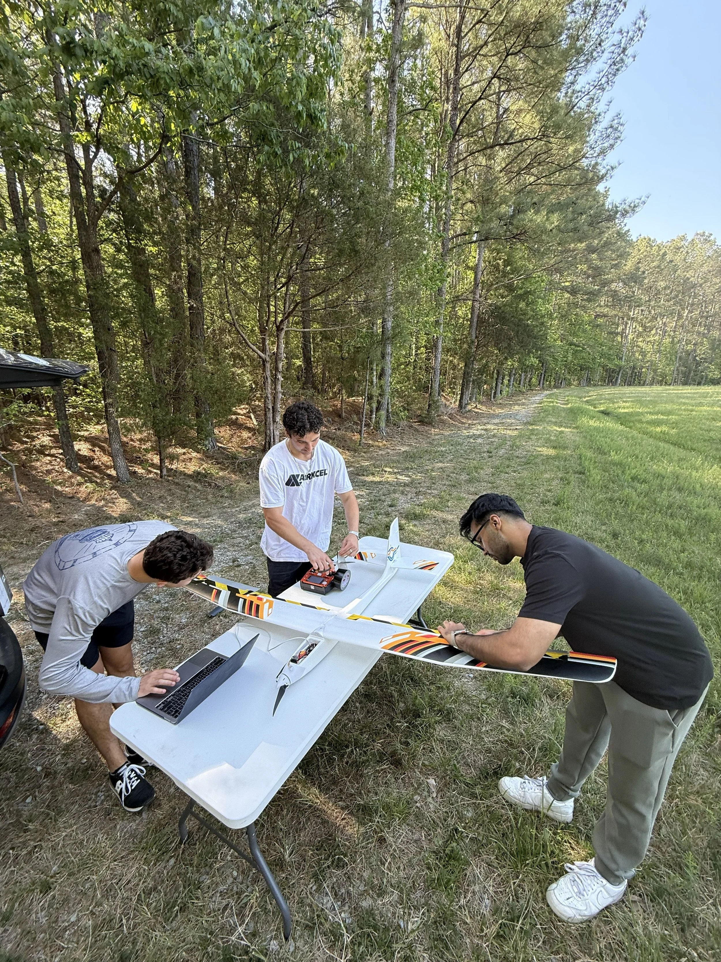
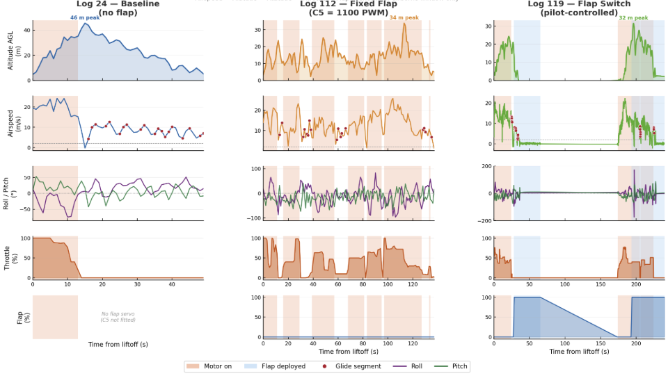
For outdoor validation, the glider was instrumented and flown in multiple configurations: the original baseline aircraft, the modified wing with the flap retracted, and the modified wing with the flap deployed. Flight logs were processed after each test to isolate unpowered glide segments, filtering out portions of the flight affected by throttle input, excessive roll, low altitude, or unreliable airspeed data.
The final flight data showed that the modified wing successfully reduced stall speed. The baseline glider had an estimated stall speed of 5.50 m/s. With the modified wing and flap retracted, stall speed dropped to 4.57 m/s, a 17.0% reduction. With the flap deployed, stall speed dropped further to 3.81 m/s, corresponding to a 30.8% reduction from baseline. This exceeded the original 10% stall-speed reduction target and demonstrated that the flap system successfully increased low-speed lift capability.
The sink rate results were less successful. Instead of achieving the target 5% reduction, the modified configurations showed higher median sink rates than the baseline. The modified wing with the flap retracted had a median sink rate of approximately 4.02 m/s, while the deployed flap configuration had a median sink rate of approximately 4.06 m/s, compared to the baseline value of 3.17 m/s. These results suggested that although the flap system improved stall behavior, the added drag, added mass, center-of-gravity shift, and outdoor flight variability limited glide efficiency.
This was one of the most important engineering outcomes of the project. The final aircraft met and exceeded the stall-speed objective, but it did not meet the sink-rate objective under the tested conditions. Rather than treating that as a simple failure, the data showed the real tradeoff behind flap integration: increasing camber and lift can make an aircraft fly slower, but without careful control of drag, mass, and center of gravity, that same modification can reduce glide efficiency.
Project Manager
Throughout the design, fabrication, and testing process, my role as Project Manager was to keep the project moving as a connected aircraft system rather than a set of isolated subteam tasks. The project involved flight science, structures, avionics, fabrication, and testing, and each area had decisions that affected the others. A flap geometry change influenced manufacturing and structural stiffness, added avionics weight affected center of gravity, and flight test requirements shaped how the aircraft needed to be integrated. My responsibility was to help the team manage those connections while staying focused on the client’s performance goals.
I coordinated weekly team progress, organized meetings, tracked deliverables, and helped translate the broad goal of “improve glider performance” into smaller engineering tasks that could be owned by each subteam. I also helped manage communication between groups so that analysis, CAD, fabrication, avionics, and testing decisions were not made in isolation. This became especially important as the project moved from early concepts into physical integration, where small design choices had immediate effects on manufacturability, weight, stability, and schedule.
In addition to managing the team, I contributed directly to the technical development of the aircraft. My work included helping reconstruct the glider wing geometry in CAD, supporting the flap and aileron design process, contributing to 3D CFD planning, helping evaluate fabrication strategies, and coordinating final integration decisions. I was especially involved in the transition from concept to manufacturable design, where the team moved from early foam and wood prototypes toward a CAD-modeled PLA control surface system that could be rapidly iterated and installed with repeatable geometry.
One of the biggest challenges in this role was balancing engineering ambition with project constraints. More complex flap systems and lighter material solutions were attractive on paper, but the team also had to consider reliability, schedule, manufacturing accuracy, budget, and whether the final design could actually be tested. As Project Manager, I helped guide those tradeoffs so the team could converge on a solution that was realistic, buildable, and measurable within the senior design timeline.
This project taught me that engineering leadership is not just about assigning tasks or setting deadlines. It requires understanding the technical details well enough to recognize dependencies, communicate risk, and help the team make decisions when there is no perfect answer. Leading this project gave me experience managing a multidisciplinary aerospace system from early problem definition through final prototype demonstration, while still staying closely involved in the hands-on engineering work.