MECHANICAL DESIGN
ABOUT THE COURSE & PROJECT
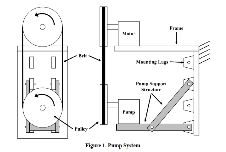
Mechanical Design (ME 321) was a comprehensive course focused on mechanical analysis techniques crucial for engineering design, including stress analysis, material selection, failure prediction, and iterative prototyping. The course combined theoretical content with a semester-long group project that challenged us to design, analyze, manufacture, and test a mechanical assembly—a pump support structure capable of handling operational loads while adhering to constraints like weight, deflection, and budget limitations. The project required rigorous calculations, iterative design processes, material optimization, CAD modeling, finite element analysis (FEA), and physical prototype validation.
PROJECT STEPS
STEP 1: FORCES AND MOMENTS
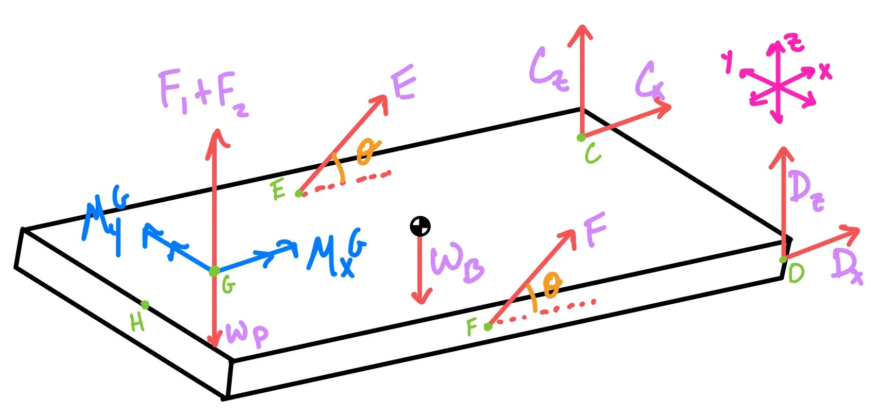
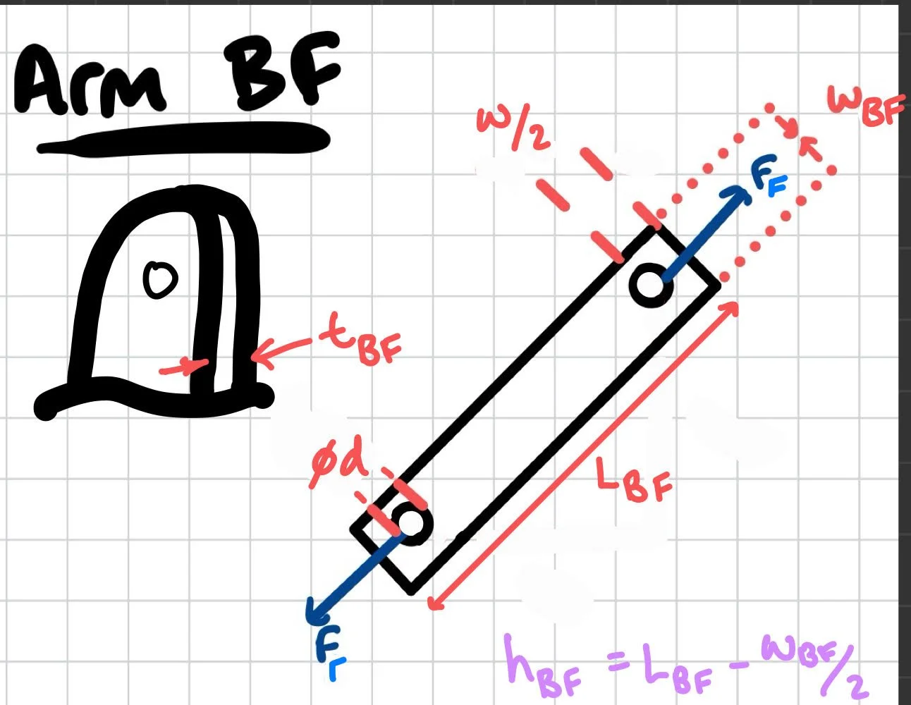
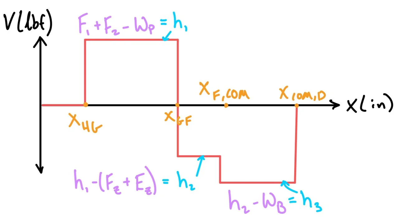
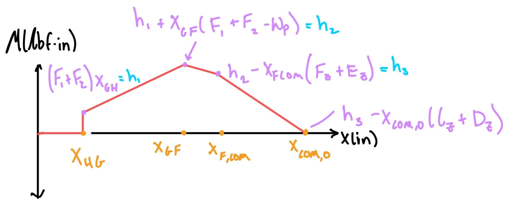
In this initial phase, we analytically solved foundational equations to determine the forces and moments involved in our pump assembly design. We began by calculating the required fluid and mechanical power to meet specific pump performance criteria (150 GPM and 60 ft head). Using detailed Free Body Diagrams (FBD), we conducted force and moment balances to understand the mechanical interactions clearly. We calculated pulley torque, forces on the support arms, and loads at connection points. Additionally, we sketched preliminary Shear Force and Bending Moment Diagrams, identifying key locations where maximum bending stresses were anticipated.
STEP 2: FAILURE & MATERIALS
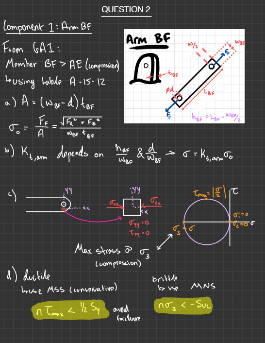
In this phase, we derived symbolic expressions to analyze stresses such as tensile, compressive, bending, shear, and torsion within each component of our pump support structure. We identified key stress concentrations—especially critical at pin holes—and determined the locations most susceptible to failure, such as the center pin slots of the platform and arm-pin connections. Using symbolic equations, we calculated nominal stresses, incorporated stress concentration factors, and derived expressions for maximum shear and principal stresses. We selected Aluminum 6061 for the platform and support arms due to its excellent strength-to-weight ratio and corrosion resistance, and stainless steel for the pins, balancing strength, machinability, and durability.
The image on the left shows the solution for the stress concentrations, principal stresses, and factors of safety for one of the two arms.
STEP 3: FINITE ELEMENT ANALYSIS VALIDATION
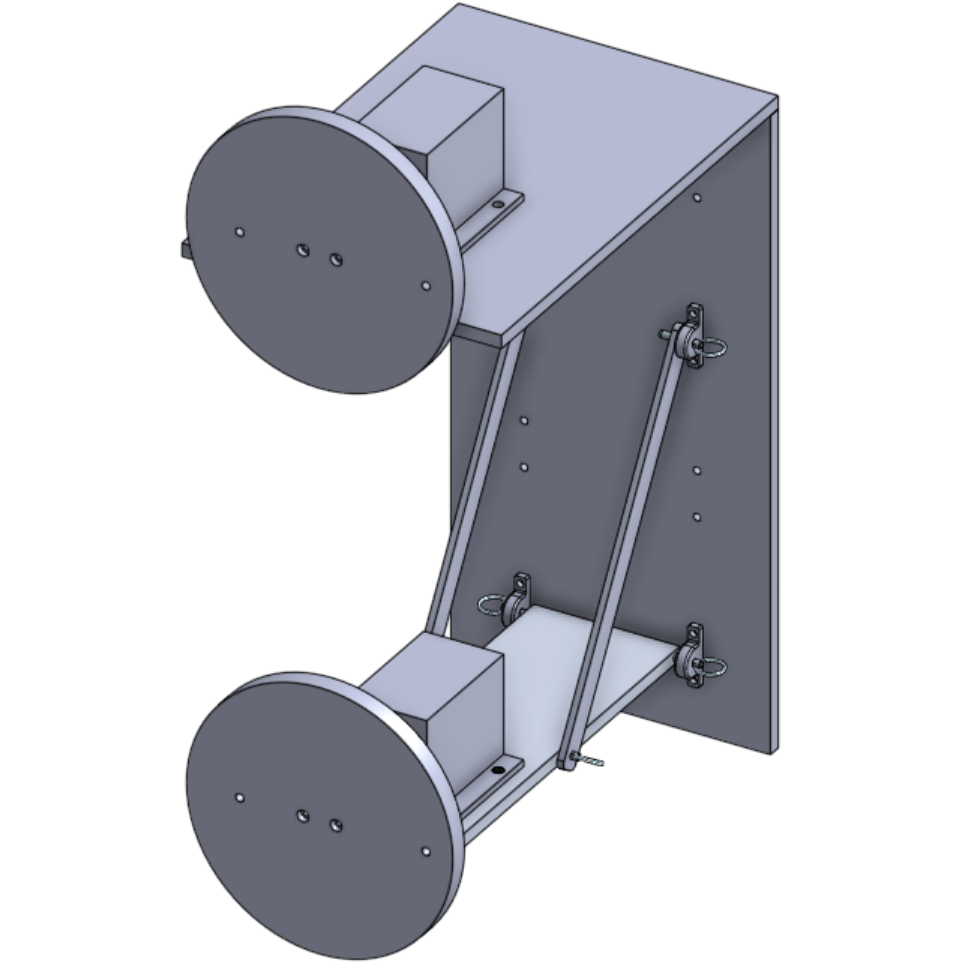
This stage involved detailed finite element analysis (FEA) simulations using SolidWorks. Initial hand calculations had predicted potential failures at critical points, particularly in the pins and platform pin slots. The FEA simulations confirmed these predictions, identifying the pins as the components most likely to fail first under increased loads. The maximum stress locations corresponded closely to our predictions, with the platform’s center pin slots and arm-pin holes experiencing peak stresses. The platform's maximum deflection under simulated loads was approximately 1.63mm, higher than initial expectations, prompting us to suggest design improvements such as adding additional pins to better distribute stresses.
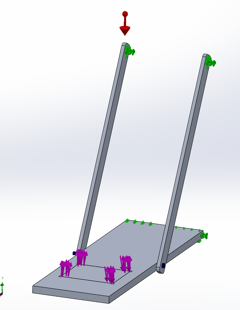
FEA SETUP
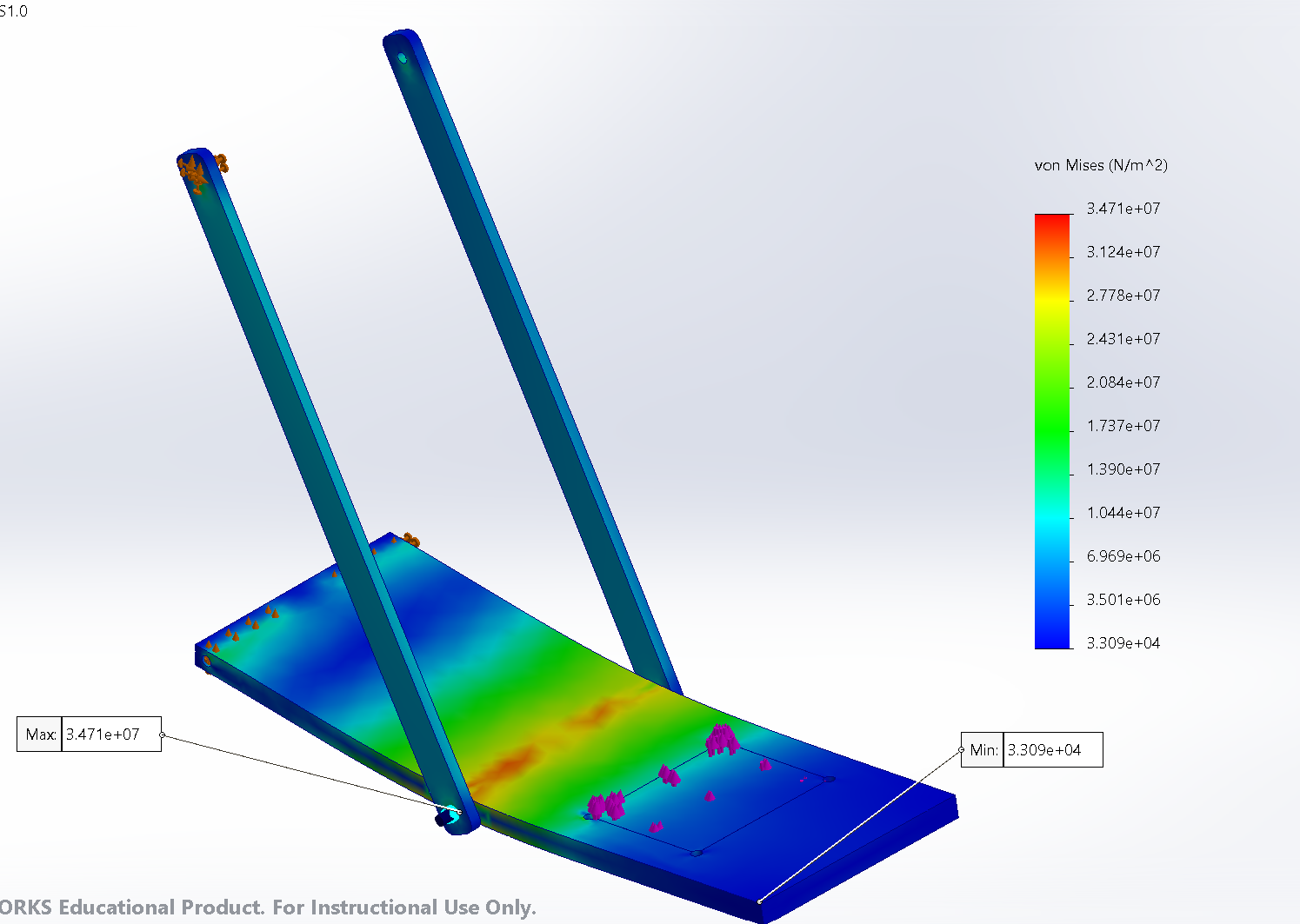
Von Mises (Stress) FEA
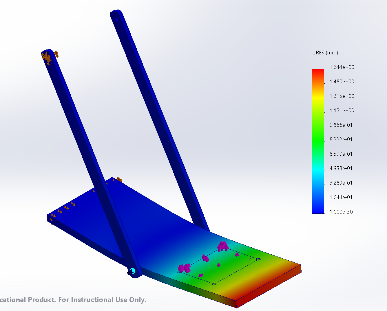
URES (Deflection) FEA
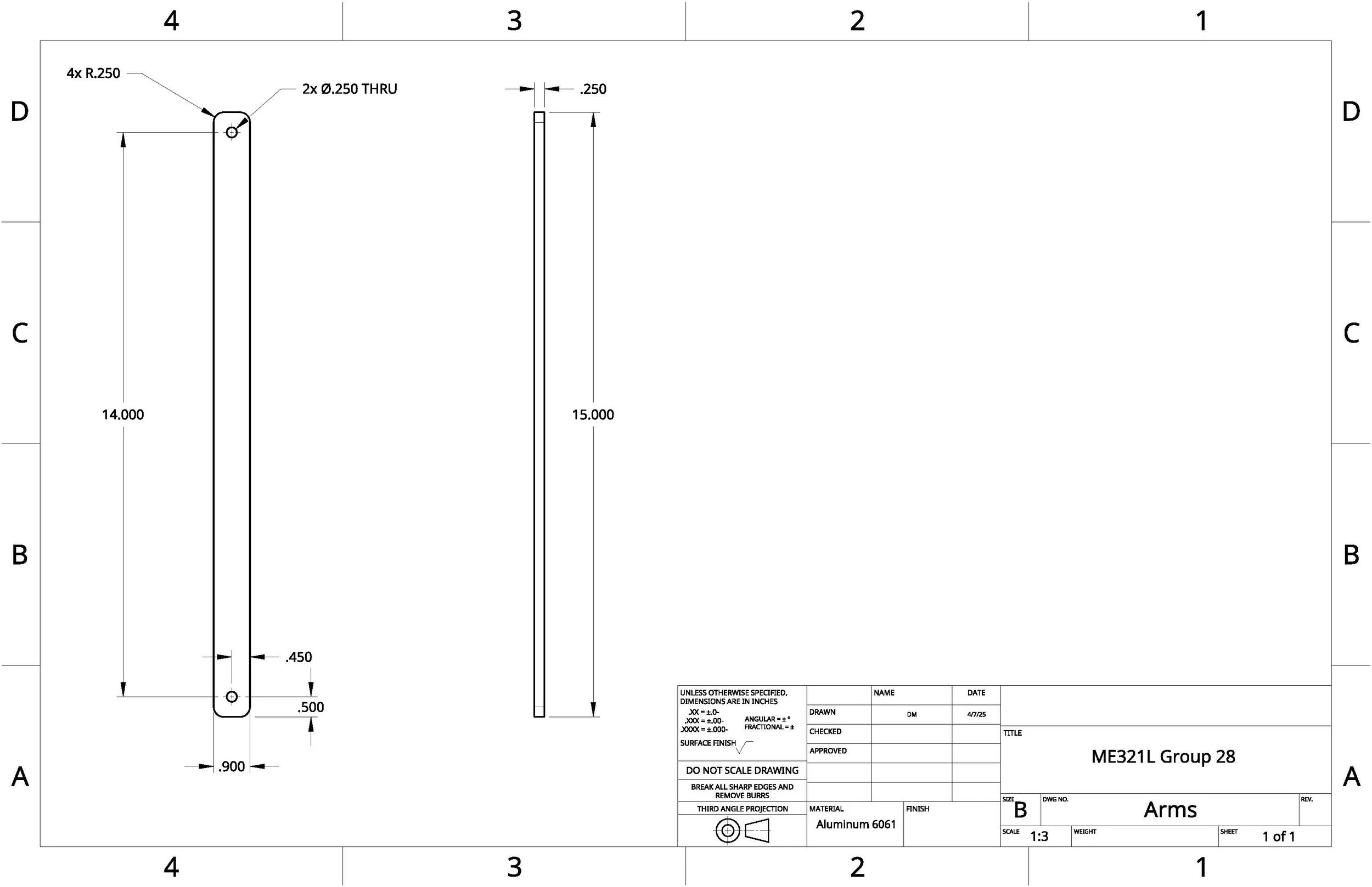
Detailed manufacturing drawings were created for each component, including the platform, arms, and pins, adhering strictly to ASME Y14.5-2018 tolerancing and dimensioning standards. We generated clear, comprehensive CAD drawings featuring assembly views, part balloons, and a thorough Bill of Materials (BOM). Each drawing provided explicit dimensions, geometric tolerances, material specifications, and necessary fabrication details to ensure seamless manufacturing and assembly.
STEP 4: MANUFACTURING DRAWINGS
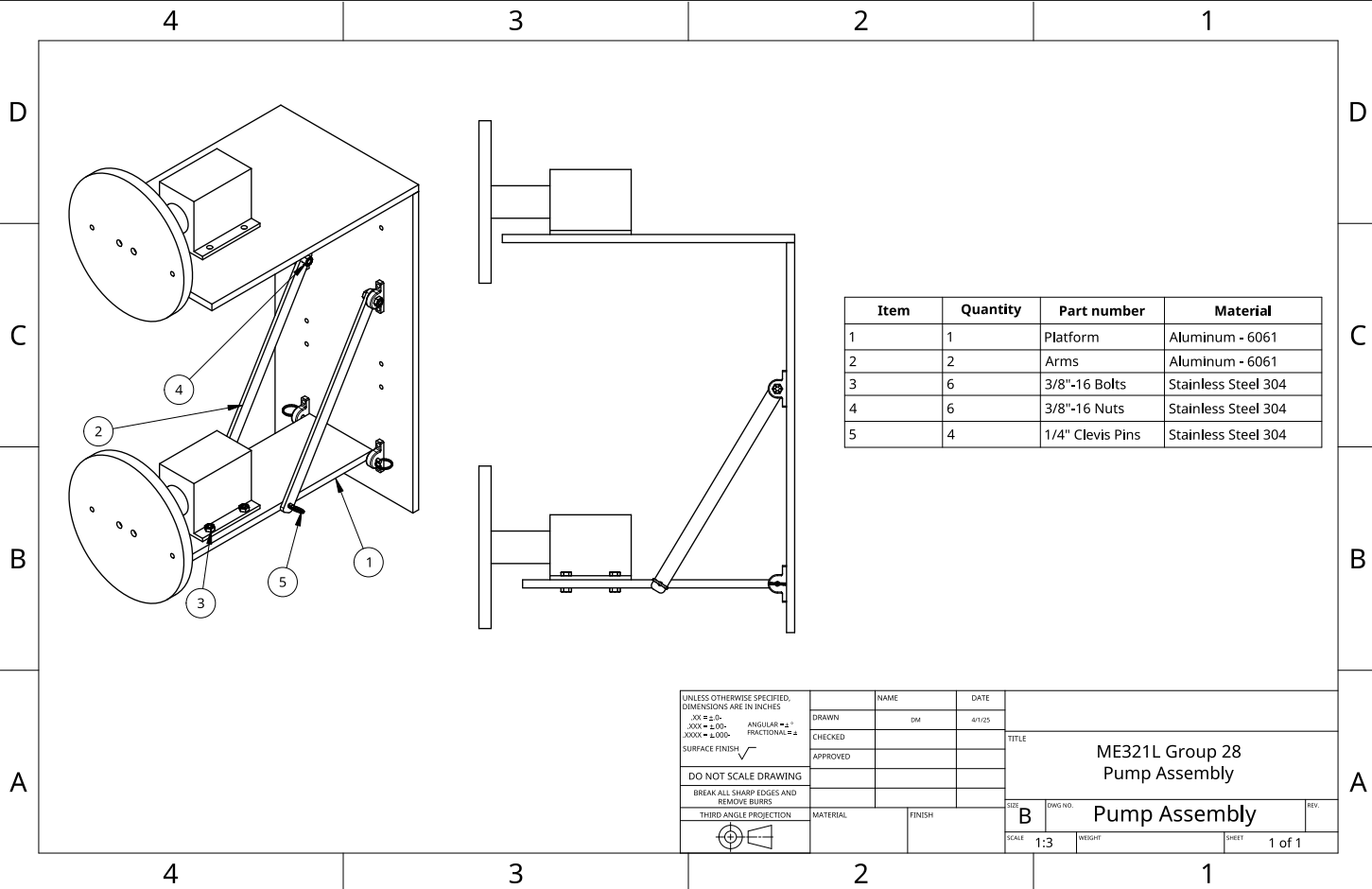
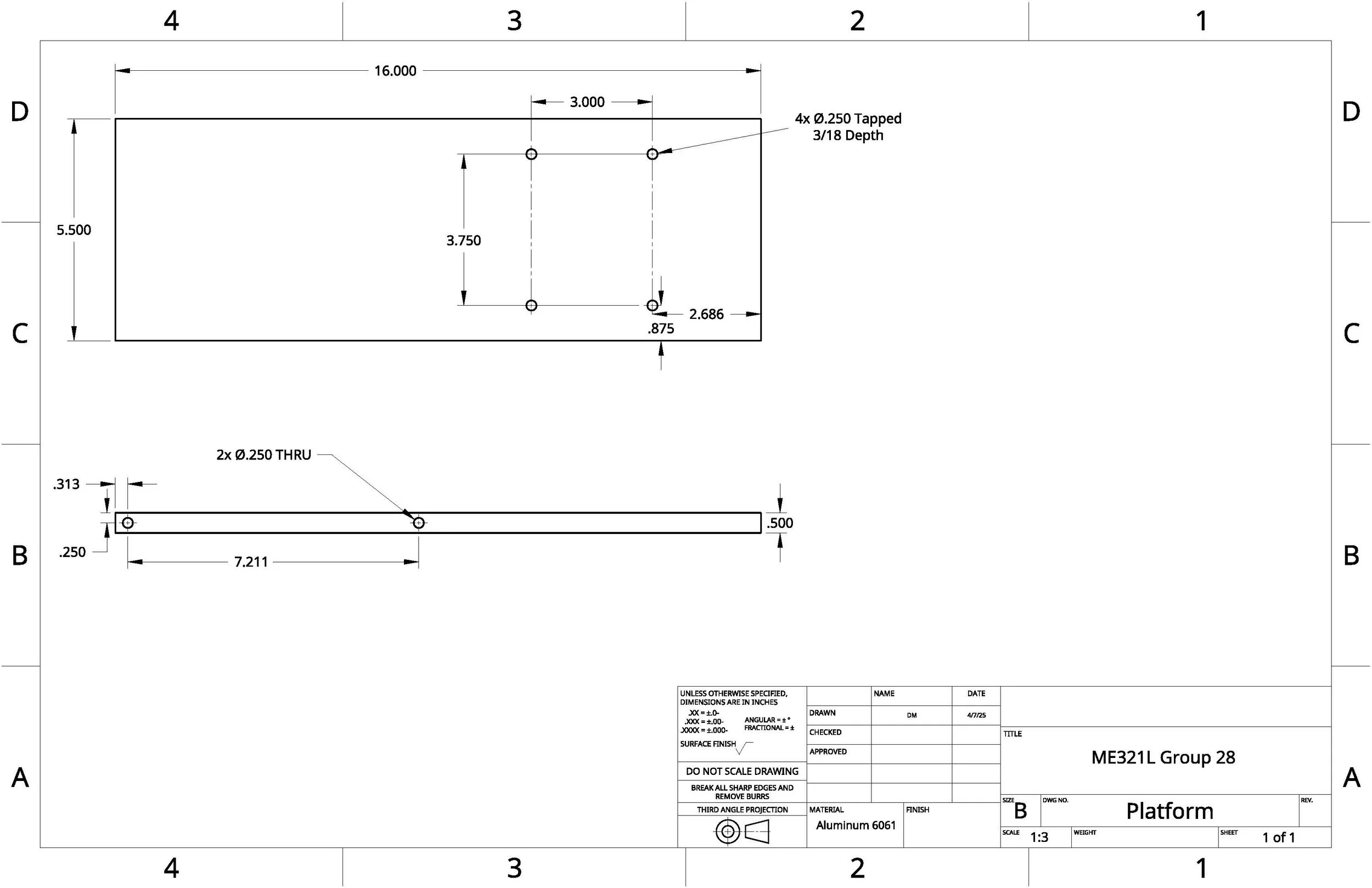
STEP 5: PHYSICAL PROTOTYPE
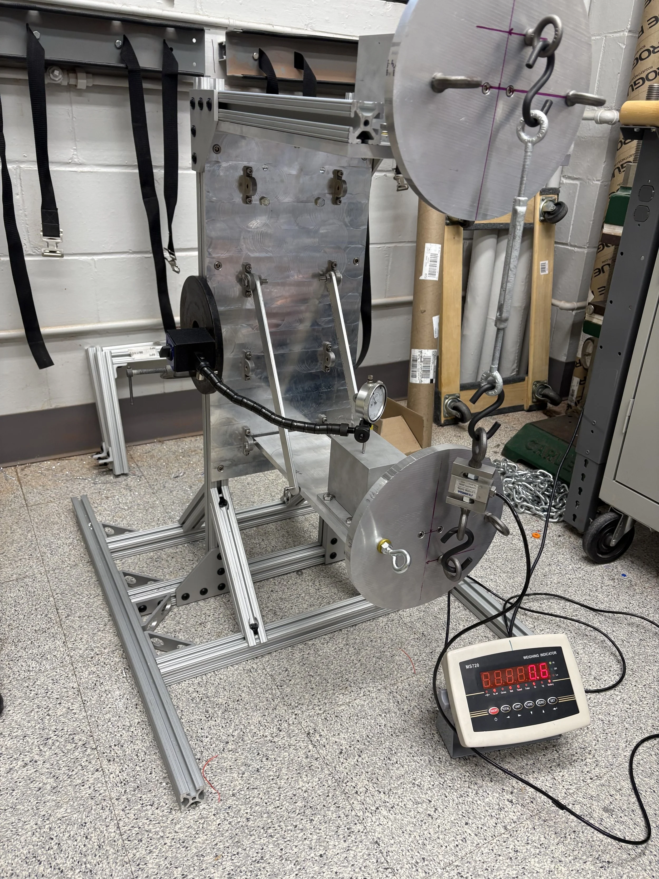
The culmination of our design effort resulted in a fully functional physical prototype. The assembled prototype weighed 5 lbs 8.2 oz, successfully interfaced with the provided mounting brackets, and maintained an overall height of 13 inches. In testing, our assembly exceeded expectations by withstanding a load of 117 lbs, demonstrating significant structural integrity. However, we observed a maximum deflection of 3.81mm, slightly beyond our ideal goal, highlighting areas for further design refinement.